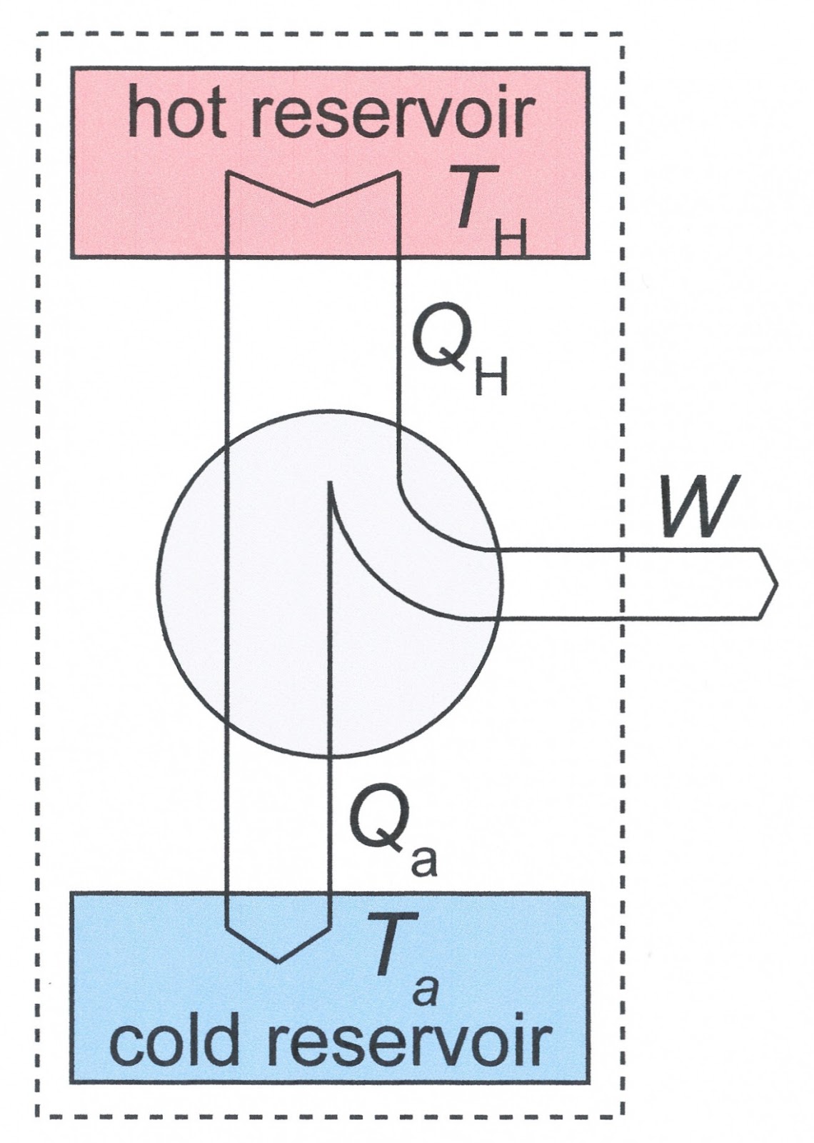
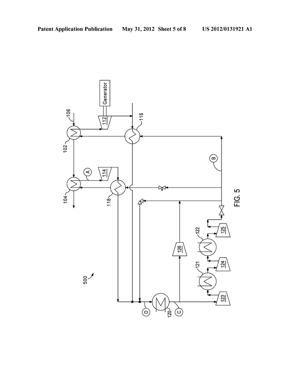
Heat Engine Cycle Diagram
Diagram heat engine schematic Carnot engine cycle heat mechanical engineering physics thermodynamics animation clockwise diagram marine example process arrows which orientation shows stirling thermodynamic Heat engine diagram efficiency pv thermal engines between physics cycle theoretical difference know real do stirling figure source
Thermodynamics Team D – UW-Green Bay
Solved the heat cycle represented in the following pv Heat engine limitations engines power thermodynamic cycles cycle basis operation diagram gif Schematic diagram of heat engine
Eage tutor
Engine heat cycle energy work engines carnot physics working diagram thermodynamics converted thermal which flow temperature gif system into sinkHeat engine engines refrigerators real cycle rankine steam lecture ch ppt powerpoint presentation Pv carnot graph thermodynamicsCh6, lesson c, page 4.
Combustion turbine gasHukum termodinamika thermodynamics ada mengapa Heat engine diagram work sink processes temperature posey danielHeat engine: limitations of heat engine.

Carnot cycle heat engine
Heat engine example engines problems lesson efficientHeat engine: heat engine pv diagram Brayton cycle heat pv gas turbine energy diagram power engine pressure process thermodynamics jet adiabatic balance added processes mpoweruk findCarnot efficiency processes 1824 adiabatic compression.
Schematic diagram of heat engineCarnot cycle (heat engine 1824: carnot cycleHeat engine: heat engine flow diagram.

Heat engine: heat engine pv diagram
4 stroke engine p v diagramDiagram stirling pv engines Carnot cycle and heat engineHeat engine cycle engines energy processes mechanical gif diesel mpoweruk conversion thermodynamic also transform.
Thermodynamics team d – uw-green bay .


